4 The Cabinet
4.1. Introduction
The eSite Modular battery cabinet (see figure 4.1) is a free-standing thermally insulated single-bay cabinet intended for telecom outdoor applications. It is the ideal way of storing and protecting valuable equipment at urban and remote sites used in critical infrastructure.
The battery cabinet is designed for use with eSite Modular Converter Units mounted on the sides of the cabinet, which use passive convection cooling for cooling of all power electronics. Thus, the cooling effect needed inside the cabinet is only to keep the batteries cooled. This is beneficial and leads to energy savings as free air cooling is way more suitable in many conditions compared to when having traditional power cores that generate heat losses inside the cabinet together with the batteries. The cooling system has user-selectable fan control modes that uses the included temperature sensors. Notifications can be sent to the user based on configurable temperature levels. The cabinet door has an alarm kit that can send notifications to the user.
The cabinet is prepared for easy integration with two Converter Units and supports all cable management and interfaces for easy and fast installation. Support for a third Converter Unit can also be prepared as an option. The cabinet is developed for Li-ion batteries and can hold up to 33U of battery capacity.
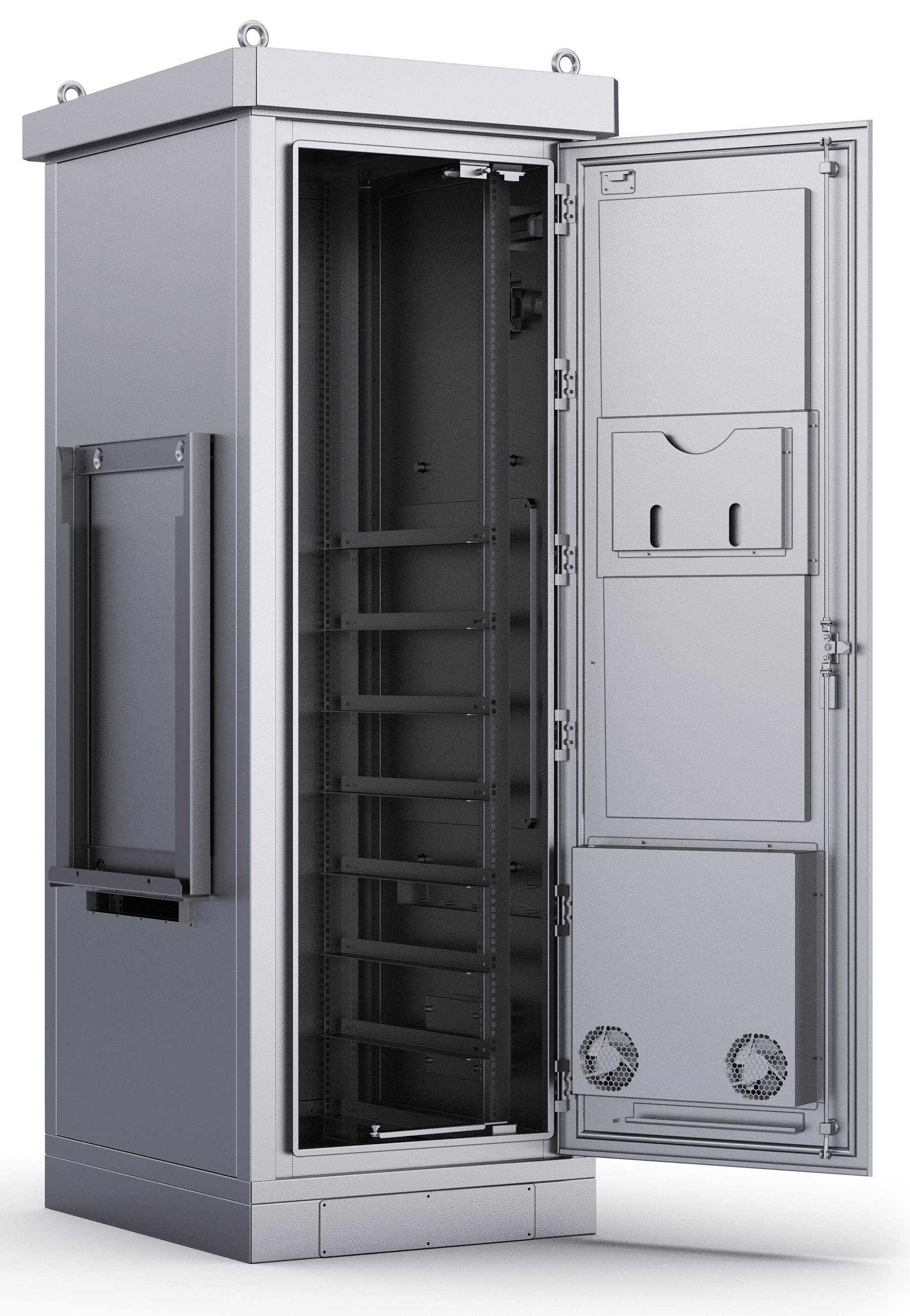
Figure 4.1. The battery cabinet opened with a mounting frame on the outside and fans visible on the inside of the door.
The lifting hooks on the top of the cabinet can be removed after installation on site as a security measure and its holes covered to eliminate risk of water ingress. The plinth covers on the lower front and back of the cabinet can be opened for easy access underneath during installation.
Two versions of the battery cabinet are currently available for shipping for most site types but tailor-made versions can also be developed to fit specific requirements such as:
• General dimensions
• Degree of intrusion protection
• Shelf types for batteries
• Free air, Heat exchanger or Air Condition cooling for cooling of batteries
• Colour, ingress protection and insulation material
• Electrical installation layout and cable entries
4.2 The Power Combiner Unit
The Power Combiner unit (PCU) is mounted at the top of the cabinet, above the battery racks but below the RMC, and hosts all DC power distribution, including the load disconnect contactors and all MCBs (see figure 4.2). The PCU acts as the electrical connection interface for the Converter Units, the battery bank and the customer load on site.
Alternative versions of the PCU can be developed upon request.
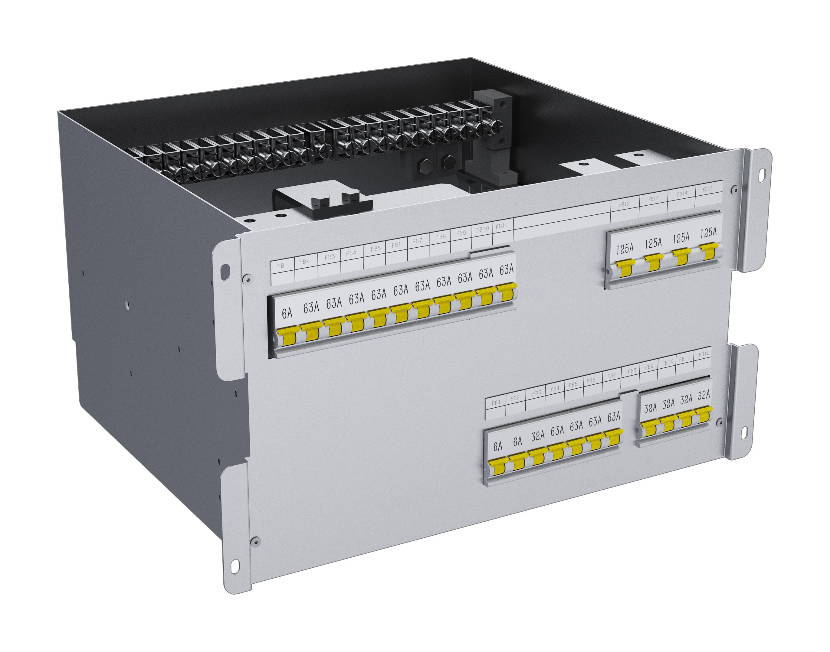
Figure 4.2 The Power combiner unit (PCU).
4.3 Technical specifications
| Power Combiner Unit (PCU) | Description |
|---|---|
| AC Input | Dual (Genset and Grid) power terminals 5 x 16 mm2 |
| Maximum Battery Current | 500 A |
| Number of battery MCB:s | Up to 10 positions (63 A) |
| Load Control | One High Priority and one Low Priority load disconnect |
| High Priority Load Capacity | 7 kW (140 A @ 50 VDC) |
| Low Priority Load Capacity | 15 kW (300 A @ 50 VDC) |
| Number of Tenants | 4 tenants with individual power measurement, 32A High Priority MCB, 63 A Low Priority MCB |
| Features | Configurable upon customer request, prepared for up to two Converter Units, mounted on rails for easy access |
| Battery Cabinet | Description |
|---|---|
| Design | IP 55, Single wall with internal insulation (20mm), solar |
| Material | Galvanized Steel, Powder Coated RAL 9016 |
| Cooling | Free Air Cooling or in combination with Air Conditioner |
| Weight | ~250 (kg) |
| Dimensions | W 700 x D 800 x H 2050 (mm) |
| Battery Capacity | 34 U x 19“ 8 mounting rails |
| Features | Door contact, LED Light, door stopper, floor mounted gland plates, earth and termination busbars, support for up to two of any combination of RSE, RE or SE |