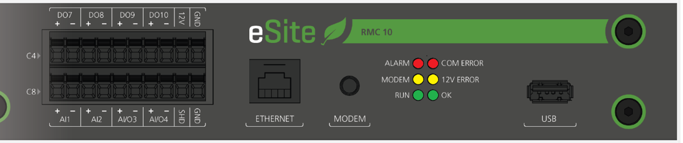
Figure 6.1. Partial view of the eSite RMC front with LED indicators
| LED name | Color | Indication | Comment |
|---|---|---|---|
| ALARM | Red | Stable light indicates that one or more internal alarms of severity error (E) or fatal (F) is active. | Access information about active alarms from the eSite Web or via eSite Tools. Take necessary action(s) to solve any issues and reset active alarms. |
| MODEM | Yellow | Stable light indicates that IP address is received correctly and that the modem is connected. | Required for communication with eSite Tools. If the LED is off, verify that the SIM card is functional and has data available and that the antenna is connected properly. |
| RUN | Green | Stable light indicates that the main control application is up and running. | Main control application starts running approximately 80 s after initial system boot. If the LED stays off or is turned off outside this timeframe, the application is not running as expected. Reboot the system. |
| COM ERROR | Red | Indicates that any expected communication is not working. Stable light indicates that the main CPU is not communicating. | Possible hardware fault. Verify that all communication cables are connected properly. |
| 12V ERROR | Yellow | Stable light indicates that internal or external 12 V supply is outside range (12 V ± 0.5 V) | Possible hardware fault. Connected sensors/devices may not receive adequate voltage supply. Measure voltage. |
| OK | Green | Stable light indicates system is operating with no active user alarms. | If this LED is off and the red ALARM LED is on, there may be issues on site that requires action. |
Figure 6.1. Partial view of the eSite RMC front with LED indicators
| Possible cause | Suggested action | Trigger condition | Reset condition |
|---|---|---|---|
| Temperature sensor or sensor cable is faulty. | Check the ambient air temperature sensor for damage, replace if necessary. | The alarm is triggered on the I/O through the analogue signal cable that connects the temperature cable to the I/O terminal. Outside 3.16 V =–39.94 °C and 0.60 V =68.24 °C the alarm is triggered. | eSite RMC I/O voltage received is 0 V or 10 V depending on temperature configuration. |
| Possible cause | Suggested action | Trigger condition | Reset condition |
|---|---|---|---|
- Battery failures. - MCB faulty. - Communication signal cable faulty. - I/O incorrect configuration. | 1) Verify the connection on the I/O terminals. 2) Ensure that the battery fuses are dimensioned for the battery short-circuit and not for the over current. 3) Check/measure the condition of each battery. 4) Ensure that the I/O configuration matches the MCB settings (Normally open / Normally closed). 5) Check the battery breaker for burning marks, short circuit etc. Replace if necessary. 6) Check the battery bank power cable connection. 7) Make sure that there are no interruptions on the signal cable. | The alarm is triggered on the I/O through the Digital signal cable that connects the MCB to the I/O terminal. | Received eSite RMC I/O voltage is 24 V or 0 V depending on I/O configuration (Normally open / Normally closed). |
| Possible cause | Suggested action | Trigger condition | Reset condition |
|---|---|---|---|
| Sensor Hardware failure. | Replace the sensor inside the cabinet (requires system shutdown). | Sensor Hardware failure. | Communication with functional current sensor. |
| Possible cause | Suggested action | Trigger condition | Reset condition |
|---|---|---|---|
1) Insufficient cooling of battery cabinet. 2) Fans or AC cooling failure. 3) Filter clogged. 4) Damaged batteries. 5) Damaged battery cabinet. 6) Door is open or not closed properly. 7) Insufficient shading of battery cabinet. | 1) Inspect fans and AC cooling for failure. 2) Inspect filter and replace if dirty. 3) Inspect the batteries for visible injuries/bulges. 4) Inspect cabinet, doors and high power cables for damages. 5) Inspect condition/existence of roof over battery cabinet/ Improve shading over battery cabinet. | The alarm is triggered at 37.0°C, the average temperature measured over 1 week. | The alarm trigger temperature conditions are: [x °C – 0.2 °C]. |
| Possible cause | Suggested action | Trigger condition | Reset condition |
|---|---|---|---|
1) Insufficient cooling of battery cabinet. 2) Fans or AC cooling failure. 3) Filter clogged. 4) Damaged batteries. 5) Damaged battery cabinet. 6) Door is open or not closed properly. 7) Insufficient shading of battery cabinet. | 1) Inspect fans and AC cooling for failure. 2) Inspect filter and replace if dirty. 3) Inspect the batteries for visible injuries/bulges. 4) Inspect cabinet, doors and high power cables for damages. 5) Inspect condition/existence of roof over battery cabinet/ Improve shading over battery cabinet. | The alarm is triggered at 42.0 °C real-time/ instantaneous measured value. | The alarm trigger temperature conditions are:[x °C – 2.0 °C]. |
| Possible cause | Suggested action | Trigger condition | Reset condition |
|---|---|---|---|
1) Insufficient cooling of battery cabinet. 2) Fans or AC cooling failure. 3) Filter clogged. 4) Damaged batteries. 5) Damaged battery cabinet. 6) Door is open or not closed properly. 7) Insufficient shading of battery cabinet. | 1) Inspect fans and AC cooling for failure. 2) Inspect filter and replace if dirty. 3) Inspect the batteries for visible injuries/bulges. 4) Inspect cabinet, doors and high power cables for damages. 5) Inspect condition/existence of roof over battery cabinet/ Improve shading over battery cabinet. | 45 °C (SS) sensor valid. | The alarm trigger temperature conditions are: [x – 2.0 °C]. |
| Possible cause | Suggested action | Trigger condition | Reset condition |
|---|---|---|---|
1) Cooling equipment might have stopped working. 2) Insufficient shading of battery cabinet. | 1) Inspect cooling equipment and ensure correct functionality. 2) Check if there is a way to increase shading. | 12 °C (SS), sensors valid | x - 2 °C |
| Possible cause | Suggested action | Trigger condition | Reset condition |
|---|---|---|---|
1) Sensor or sensor cable is faulty 2) The battery cabinet temperature is severely high. | 1) Make sure that the sensor and sensor cables are not damaged. 2) Check the battery cabinet for possible causes to high temperature. | The alarm is triggered on the I/O through the analogue signal cable that connects the temperature cable to the I/O terminal. | eSite RMC I/O voltage received is 0 V or 10 V depending on temperature configuration. |
| Possible cause | Suggested action | Trigger condition | Reset condition |
|---|---|---|---|
| There is another power source connected to the system, which is not controlled by the eSite RMC. | Check on the site if there is any other power source connected. Disconnect the power source. | Default 60 V. This threshold is temperature compensated according to the battery calibration. | The alarm trigger temperature condition is: x –0.5 V. |
| Possible cause | Suggested action | Trigger condition | Reset condition |
|---|---|---|---|
- Genset has failed to start. - Genset failed to produce sufficient power to customer load and battery bank. - Grid not available. | 1) See Genset Failed to Start alarm. 2) Verify genset rating settings. 3) Verify grid fuse max current configuration. | Default <= 46.5 V (configurable). | Default >= 48.5 V (configurable). |
| Possible cause | Suggested action | Trigger condition | Reset condition |
|---|---|---|---|
- Battery voltage sensor faulty connected. - Reversed polarity. | 1) Check the sensor installation. 2) Verify the polarity of the sensor cables. 3) Check the connection to the RMC. 4) Check the fuse on the negative side of the battery voltage sensor cable. | Sensor voltage >70V or <10V | N/A |
| Possible cause | Suggested action | Trigger condition | Reset condition |
|---|---|---|---|
- High outside temperature (>Nominal Temperature). - Direct sunlight placement. - Close to a heat source. - Dirty heat sink. - Hardware malfunction. | 1) Improve the shading over the RMC unit if required. 2) Make sure that the RMC is not placed close to a heat source. 3) Contact first line support. | Internal temperature is too high. | Internal temperature is lowered to acceptable level. |
| Possible cause | Suggested action | Trigger condition | Reset condition |
|---|---|---|---|
- Error in internal databases. - Trying to access eSite Web too soon after a reboot. | 1) Reboot main controller to restore database. 2) Press the "Factory reset" button, see section Shutdown/Reset. | Database Open/read/write error. | No errors at init. |
| Possible cause | Suggested action | Trigger condition | Reset condition |
|---|---|---|---|
| User connected alarm indicator relay has tripped. | N/A | User defined trigger condition(s). | User defined reset condition(s). |
| Possible cause | Suggested action | Trigger condition | Reset condition |
|---|---|---|---|
| Fuel tank has been refilled | N/A | 4 % fuel increase is detected between a rolling period of 1800 sec. | The alarm will reset itself within one hour after the filling was detected. |
| Possible cause | Suggested action | Trigger condition | Reset condition |
|---|---|---|---|
| Fuel theft or leakages. | Check the fuel tank and the fuel sensor on site. | 4 % fuel decrease is detected between a rolling period of 1800 sec. | The alarm resets itself after a refill. |
| Possible cause | Suggested action | Trigger condition | Reset condition |
|---|---|---|---|
| Not enough fuel in the tank. | Refill fuel. | Default value: below 300 litres (configurable). | Default value: 300 + 20 litres (configurable). |
| Possible cause | Suggested action | Trigger condition | Reset condition |
|---|---|---|---|
- The Fuel Sensor is disconnected. - The Fuel Sensor is not installed correctly. - The Fuel Sensor is faulty. | 1) Check sensor installation. 2) Check the sensor polarity. 3) Verify the sensor configuration. 4) Check if the sensor is faulty. | The alarm is triggered on the I/O, through the analogue signal cable that connects the fuel sensor to the I/O terminal. | eSite RMC I/O voltage received is 0 V or 10 V depending on fuel sensor configuration. |
| Possible cause | Suggested action | Trigger condition | Reset condition |
|---|---|---|---|
| Not enough fuel in the tank. | Refill fuel | Default value: below 200 litres (configurable). | Default value: 200 + 20 litres (configurable). |
| Possible cause | Suggested action | Trigger condition | Reset condition |
|---|---|---|---|
- Communication cables between eSite RMC and genset are damaged. - Genset start battery is empty. - Incorrect Genset Modbus settings. | 1) Check the communication cables from eSite RMC to genset for damage. 2) Check the genset and repair if required. 3) Ensure that the Modbus configuration matches the genset control panel settings. | No communication response from genset. | Restored communication. |
| Possible cause | Suggested action | Trigger condition | Reset condition |
|---|---|---|---|
| Alarm depending on Genset type and I/O configuration. | 1) Check the genset to make sure it is not damaged. 2) Make sure that there are no interruptions on the signal cable. 3) Ensure that the I/O configuration matches the MCB settings (Normally open / Normally closed). | Genset external alarm trigger condition(s). | Genset external alarm reset condition(s). |
| Possible cause | Suggested action | Trigger condition | Reset condition |
|---|---|---|---|
- Genset battery empty or faulty. - No fuel. - Genset alarm. - Communication to genset controller broken. - Power cables between the eSite Modular system and Genset are faulty. - The genset is manually forced off on site. | 1) Check the genset battery and generator system. Charge the battery if necessary. 2) Fill up fuel. 3) Check and reset error in genset. | No feedback from genset is detected by the rectifiers for 5 minutes. | The alarm resets itself when Genset input AC voltage is detected. |
| Possible cause | Suggested action | Trigger condition | Reset condition |
|---|---|---|---|
| Genset is manually forced to run by pressing the start button on the genset panel. | 1) Make sure that the genset is in auto mode / remote control mode. 2) Verify the start signal from eSite RMC to genset. | Genset is commanded to stop but eSite RMC is still detecting incoming AC voltage from Genset for 5 minutes. | Inactive start command and no AC voltage has been detected from Genset for 1 minute. |
| Possible cause | Suggested action | Trigger condition | Reset condition |
|---|---|---|---|
| Maintenance has not been performed. | Perform genset maintenance according to genset documentation. | Default 0 hours left to maintenance. | The timer for genset maintenance is reset. |
| Possible cause | Suggested action | Trigger condition | Reset condition |
|---|---|---|---|
– Grid power is temporarily out. - Grid breaker tripped. | 1) Check if the grid provides power. 2) Check grid breaker. Repair if necessary. | AC Voltage and frequency input is out of range for 10 sec. | AC Voltage and frequency input is in range. |
| Possible cause | Suggested action | Trigger condition | Reset condition |
|---|---|---|---|
– System voltage has dropped below threshold. - No incoming power to the eSite Modular system is available. | Make sure that the power sources are working. | Default 43.5 V. | Default 48 V. |
| Possible cause | Suggested action | Trigger condition | Reset condition |
|---|---|---|---|
– The customer load is not installed correctly. - Incorrect use of High priority load and Low priority load. | 1) Verify the customer load connection on site. 2) Consult the Installation manual for correct use of High priority power and Low priority power. | 1.5 kW for 10 sec | x – 100 W |
| Possible cause | Suggested action | Trigger condition | Reset condition |
|---|---|---|---|
| I/O hardware fail. | - Make sure you have the correct SW version installed. - Replace eSite RMC. | No communication response from I/O. | RMC with correct SW installed. |
| Possible cause | Suggested action | Trigger condition | Reset condition |
|---|---|---|---|
| Tenant is drawing more power than configured. | 1) Check/measure the total power load connected to the eSite Modular system on site. 2) Reduce the total power drawn from the system. | Default load >= 5kW for 10 sec (configurable). | Alarm trigger temperature conditions are: x– 100 W. |
| Possible cause | Suggested action | Trigger condition | Reset condition |
|---|---|---|---|
| Customer load is drawing more power than configured. | 1) Check/measure the total power load connected to the eSite Modular system on site. 2) Reduce the total system power drawn. | Default load = 10 kW for 10 sec (configurable). | The alarm trigger temperature conditions are: x– 100 W. |
| Possible cause | Suggested action | Trigger condition | Reset condition |
|---|---|---|---|
- System voltage has dropped below threshold. - No incoming power the eSite Modular system is available. | Make sure that the power sources are working. | 45 V + 300 sec | The load is reconnected when battery voltage is above 48 V and produced current from the rectifiers is 20 A within 30 sec or battery voltage is above 52 V. |
| Possible cause | Suggested action | Trigger condition | Reset condition |
|---|---|---|---|
- Unregistered Converter Unit - Converter hardware fail - CAN communication cable connection faulty | Replace and/or properly connect CAN cable. Replace Converter Unit. | No communication response from power converters. | Active communication with registered Converter Unit. |
| Possible cause | Suggested action | Trigger condition | Reset condition |
|---|---|---|---|
– High outside temperature (>Nominal Temperature). - Direct sunlight placement. - Close to a heat source. - Dirty heat sink. - Hardware malfunction. | 1) Improve the shading over the Converter Units if possible. 2) Make sure that eSite Modular system is not placed close to a heat source. 3) Clean the heat sink according to the maintenance section 4) Contact first line support. | Too high rectifier internal temperature. | Normal rectifier internal temperature. |
| Possible cause | Suggested action | Trigger condition | Reset condition |
|---|---|---|---|
| Rectifier hardware fail. | Replace eSite Converter Unit. | Hardware faulty | Converter Unit replaced and communication restored. |
| Possible cause | Suggested action | Trigger condition | Reset condition |
|---|---|---|---|
| Incorrect solar panel installation. | Measure the array voltage and ensure that not too many panels are connected in series, thereby exceeding the array voltage range. | Voltage exceeding the threshold. | Automatically cleared when trigger condition is solved. System check every 10 min. |
| Possible cause | Suggested action | Trigger condition | Reset condition |
|---|---|---|---|
| Faulty connected solar array. | 1) Measure voltage to see the polarity of the array. 2) Check the connection cables. | Reversed polarity detected. | Automatically cleared when trigger condition is solved. System check every 10 min. |
| Possible cause | Suggested action | Trigger condition | Reset condition |
|---|---|---|---|
| Solar converter hardware failure. | Replace eSite Converter Unit. | No communication response from solar converter. | Converter Unit replaced and communication restored. |
| Possible cause | Suggested action | Trigger condition | Reset condition |
|---|---|---|---|
| Solar converter hardware failure. | Replace eSite Converter Unit. | Hardware faulty. | Converter Unit replaced and communication restored. |
| Possible cause | Suggested action | Trigger condition | Reset condition |
|---|---|---|---|
| Solar hardware failure. | If the solar voltage is higher than system voltage, the system will still be safe and run at degraded performance. If the solar voltage is lower than system voltage, the batteries might become overcharged witch can be unsafe and shorten the lifetime of the batteries. Ask an admin to check this in diagnostics tab. | Any of the solar converters measures its voltage ±1 V or more compared to system voltage | Voltage diff <± 1 V |
| Possible cause | Suggested action | Trigger condition | Reset condition |
|---|---|---|---|
| Over voltage from genset or grid has tripped the surge protection (SPD). | 1) Check if surge protection has tripped, replace if necessary. 2) Check signal cables between I/O and the surge protection (SPD). | The alarm is triggered on the I/O through the Digital signal cable that connects the surge protection indication to the I/O terminal. | eSite RMC I/O voltage received is 24 V. |
| Possible cause | Suggested action | Trigger condition | Reset condition |
|---|---|---|---|
– CAN communication signal cable faulty. - Sensor hardware failure. - Current sensor option enabled but no sensor installed. | 1) Make sure that there are no interruptions on the signal cable. Replace if necessary. 2) Verify that there is a sensor installed. 3) Check the ID of the current sensor. 4) Make sure the sensor is not damaged. Replace if necessary. 5) Check the configuration to match installed sensors. | Sensor hardware /Communication failure. | Communication with sensor is established, correct current measurement values data. |